
PROJECTS
TEAM HAUFF

VICTAIR MISTIFIER GEARBOX
Victair Mistifiers are designed, engineered, and manufactured by H.F. Hauff Co. Inc. in Yakima, WA. where they have been manufactured and sold since 1965. Hauff’s commitment to manufacturing the best sprayer on the market was the driving motivation of this project.
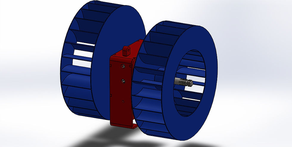
The engineering of this gearbox was to optimize the overall design and function of the Victair Mistifier orchard and vineyard sprayer. This dual output gearbox is specifically motivated by lean manufacturing. The gearbox will simplify the overall design of the sprayer. It is replacing 19 major components with 8, which will decrease the overall cost of the system. This will make the system more efficent to manufacture, by saving assembly time, and materials.
ANALYSIS
For this project, the shafts were designed and analyzed to try and use the least amount of material possible. The shafts were optimized for size using 𝐷=[ 32𝑁𝜋∗√[[𝐾𝑡𝑀𝑆′𝑛]2+34∗[𝑇𝑆𝑦]2]] 1/3 out of Robert Mott’s textbook, “Machine Elements in Mechanical Design”.
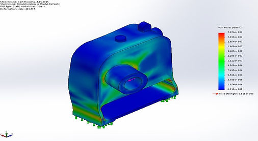
The gears were analyzed using a spreadsheet supplied by Mott as well. However, after careful examination of a similar gear box, it was discovered that additional unnecessary safety factors were being used in the spread sheets. The way to combat this was to lower our design Hp to 45 Hp instead of 60. The housing was analyzed using finite element analysis in a SolidWorks Model.
CONSTRUCTION
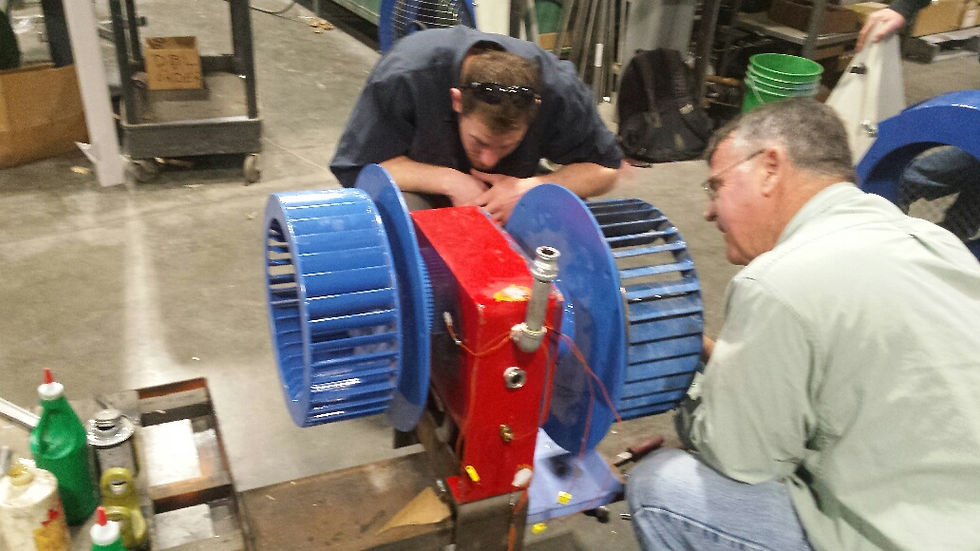
A prototype gearbox was manufactured at H.F. Hauff co. This version of the gear box was fabricated form 3/8” steel plate instead of cast iron. In addition the gears were modified to be able to cut them on a laser table. In order for this to be possible the gears had to be redesigned as spur gear sets that have the same center distance as the helical gears that were originally engineered. The gear sections were then cut out of ¼” plate on the laser table and bolted together to form complete gears.
TESTING

MATERIAL SELECTION
After applying basic statics to the bearings in the gearbox, the forces at each bearing were determined. This was instrumental in the bearing selection process, but also benefitial when apply the FEA in solidworks to the model. The FEA helped determine that the Housing will be manufactured out of cast aluminum. At four times the calculated load in the worst possible location on the housing, FEA determined that a Ductile Iron gearbox would withstand the forces with a safety factor of 24. The cast aluminum would withstand the same forces with a safety factor of 3, but weigh half as much. Priced out casting comparisons determined that the ductile iron casting would cost 70% of the aluminum version. However, aluminum is easier and faster to machine, lighter for shipping weight and moving it around the shop. An additional benifit, is the fact aluminum has better heat dissipation properties than ductuile iron. For all these reasons, it has been decided to cast the housing out of aluminum.
The Victair Mistifier gearbox was run at 540 rpm and powered using the PTO off an 80 HP tractor. The gearbox and fans were mounted to a stationary cart while being tested. Spray was not used during the testing. The gearbox was powered for two testing periods.
The gearbox was constructed with mock gears. The design calls for helical gears. However, for initial testing laser cut spur were made out of ¼” steel plate and bolted together to achieve the same dimensions as the helical designed gears.
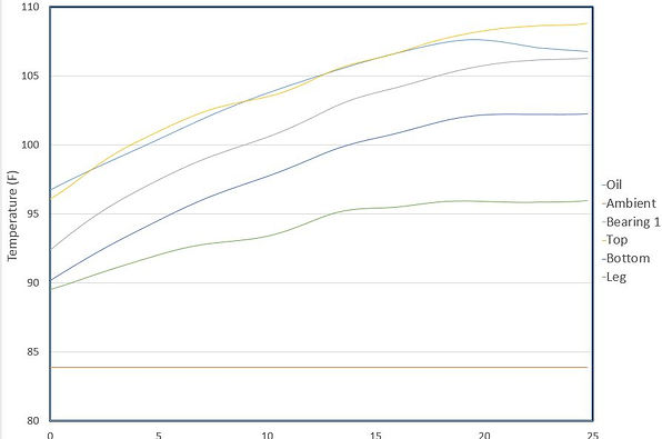
Temperature data was taken in six locations every 15 seconds while power was feed into the gearbox. The data was acquired using a Fluke Hydra Logger device and Logger software. An infrared temperature gun gave us additional temperature data. An airspeed pitot measured the airspeed out of the fans
Test Run 1
The gearbox ran under full load with both fans. The concept of the design was proved to be valid. The test period was cut short, due to excessive heat at the input shaft and hollow shaft. It was predetermined that there would be added friction at the input and hollow shaft locations. This was due to a machining error in the hollow shaft. The inner diameter of the hollow shaft bore was not to spec. When the plain surface bearings were assembled into the hollow shaft, the input shaft no longer fit through. The Teflon surface of the bearings had to be bored out in order for the input shaft to fit through the hollow shaft. Furthermore, the outside diameter of the hollow shaft was also off by a few thousandths. This caused the keyless hub to fit tighter on the shaft. This added force crushed the hollow shaft and clamped down on to the input shaft.
Even with the machining errors, the gearbox design functioned correctly and dissipated the heat generated by the gears and bearings.
Test Run 2
Fan 2 was removed from the gearbox. The Hydra Logger was set up and temperature data was acquired. The gearbox operated effectively, until an interferience fit between a gear and shaft gave. Furthermore, there was oversight on the design when considering the heat expansion of the hubs themselves. The test determined that a design revision must occur at the keyless hubs.